So what a project. Jeez man. I did indeed drop the subframe. You can weld in place but vertical tig welds are harder, and I had to preheat because I don't have a 300A welder. My shocks and control arms were already out at that point due to a planned shock replacement...haha that was supposed to be it. I had one crack in the driver side LCA small bushing arm forward tab...in that sharp radius. I welded up the outsides only on ALL arms, left and right sides. Even though those areas weren't cracked I don't ant to do this again in 2 years. So a total of 8 welds. I then heat treated the joint both sides to help normalize the stresses induced during the welding process. The casting used by GM is heat treatable and so 4043 aluminum filler rod works well. If the bead is deep enough there is really no need to do both sides. It will just add more heat to the structure and besides the new crack formation area will now be at the base of the beads, where it blends with the base metals at the outer edges. My welds are not perfect by any means but I think they will work and are gonna be stronger than the previous joint...especially the cracked one!
View attachment 158360
I installed the Creative steel red control arm bushing kit. They include these stainless steel shims or washers and the Nord lock washers that work pretty well. But the arms still compress during the torqueing procedure, 141 ft.lbs. The arms are always going to bend inward during tightening because there is compliance in the bushings...no matter the duro they will still compress somewhat. I imagine that with age the OEM GM bushings become more compliant and this induces more flexing causing cracks to form. They are indeed very flimsy joints, poorly machined to begin with. And then stuff 556hp into there.
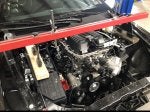
While I was at it I figured I might as well replace the motor mounts. Took them out and they were both split, I thought that was perhaps part of the design. Maybe the weight compressed the two parts together or something. But nope, the new ones are completely solid. I used the genuine GM replacements.
At each point I'm like sh*t I have this apart might as well put these in right? So what started as just worn shock replacements ended up being:
- Shock replacement
- Eibach lowering spring installation
- CS control arm bushings upper and lower
- New ball joints upper and lower
- Welded up subframe
- Replaced motor mounts
- New sway bar bushings
Got it back on the road after a long winter hibernation and two week front end overhaul on Tuesday and now the rear differential is grinding. I drained barely half quart of burned up oil out. I guess checking the rear diff level isn't part of the pre-sale inspection process at some dealerships. Anyone have a rear diff for sale?