Cadillac CTS-V Forum banner

Anyone try a aux. fuel pump intank?

65K views 132 replies 29 participants last post by  Cadispeedster  
#1 ·
Was wondering if anyone has tryed to install a aux. fuel pump in-tank?
I was thinking a 3rd pump in tank that is boost activated if you use a AEM 320 or a walbro 416 as the 3rd pump
and add a bulk head fitting in top of module for the wiring and a y block under the module to connect the aux. pump and the twins
being they are saying the factory lines are not the limitation it should work. I already have the AEM twins in-tank so adding a 3rd in
the bucket or attached to the bucket should not be a issue. If I mounted it on the outside of the bucket id use the holley hydromat so
there would be no pump starvation. I mean if the aux pump works outside tank why would it not work on the inside of tank?
 
#4 ·
Thats what I thought but I have no experience with them if you use the holley hydro mat with the aux pump you don't need a bucket with it.it will pick up any fuel that touches it.
 
  • Like
Reactions: MYV
#6 ·
Yes I know the dsx system is a proven solution to 800hp on e85. But it seems to be over complicated when it does not need to be drilling the tank mounting a pump outside and then all the lines. I just think if it's all done with the module it's less complicated and is doing the same thing or better because a walbro 416 will out flow thw bosch 044 pump. And less chance of a leak with no lines outside tank and no hole in bottom of tank. Sorry I used to own my own shop and am used to building stuff rather then buying stuff.

George
 
#8 ·
If you are used to building stuff you're probably familiar with the concept of sumping a tank...which is a *slightly* bigger hole to deal with than a simple drill and pipe tap. Modern sealants are absolutely astounding.

You have to try amazingly hard to fuck up a DSX kit. Like. Really hard. You can't make it any simpler than it is.
 
  • Like
Reactions: MYV
#11 ·
I guess the test would be to a before and after once my heads and cam package is installed. I should be 800+ hp on e85 with I'd 1000 injector and see what the idc need to achieve a lambda of.82 and the ablity to maintain fuel pressure and compair the logs. I will have the 2 aem pumps in the factory bucket with a 18 volt bap vs 2 aem pumps in factory bucket with bap off and a walbro 460lph pump added to factory line in-tank and boost activated to come on.
 
#12 ·
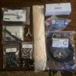
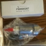
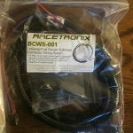
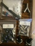
Aux fuel system

Well I have gathered most of the components for my aux. In tank pump have spent about $390.00 maybe a couple more bucks for a relay and some clamps and I should be a ready to go.
 

Attachments

  • Like
Reactions: MYV
#15 ·
Inspection of fuel bucket and fuel system

So I started to do my fuel system modification and noticed a couple thing.

First do not try to open tank cover with 1/2 tank or more there will be fuel.

I drain ed tank by putting line on test port and ran car the car will not keep bucket filled once you get to 1/8 tank so no wot at 1/8 tank of fuel

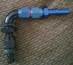
The 90deg fitting is the biggest restriction out of the bucket it reduce down to 3/16 to a quarter inch so no matter how much pump you put in the bucket you will not be able to supply the demands need of the engine.

So this is why the aux. Pump kits do so well they bypass the restrictions.

But I am creative and like to think outside the box and will be changing out the 90 deg fitting with a full flow 90deg and seeing how that does before I add my 3rd pump intank I want to see the difference with just the fitting change.
 
#18 ·
so 2 aem pumps at 320lph each are good for 169 gph.
.260 line is good for 160 gph
.220 line is good for 128 gph
the difference of 32 gph is 121 lph so the choke is affecting fueling greatly.

enought calculations ill get us some real world results.

george
 
  • Like
Reactions: MYV
#21 ·
You going to remove the ribbed hose from inside that connects to the module, then run a hose up to a bulkhead in the top hat?

If so that hose will need to have some slack inside the basket I'd think.
 
#23 · (Edited)
Yeah I saw that you found it in the plastic elbow.
I was just thinking it would be easier to replace the entire ribbed hose where it connects to the pump housing inside the basket, than to keep the ribbed hose and try to connect it to a new 90* bulkhead on the top hat.

Sounds like that's what your doing. What kind of connection you going to use for the new flex hose to the pump housing? Still TBD?

I know originally that ribbed hose is like heated and pressed on or something.
 
#24 ·
I have a couple length 10 mm flex hoses comming and I'm going to use a 6an slip lock fitting to Attach to the an bulkhead and have special epoxy to use with the an sealing washers so there in no leak on bulkhead. The new fuel line quick connect came today and it is .295 I'd vs the stock .220 I'd the stock fitting is. So I'm still waiting on parts.

George
 
#29 · (Edited)
The mass flow rate is definitely going to be affected by the .22" restriction, but a calculation I did in Solidworks using the standard Bernoulli equations provided a 15psi pressure drop when trying to flow 160GPH of fuel through a 15 foot hose @ .295" (standard 3/8 hose ID). I used plastic wall pipe coeffecient and gasoline fuel density. You would have to command 80psi at the pump, to even see 65psi at the rail (if the equation is correct). Since orifices create pressure differentials and impede mass flow to a degree, you never know if your next restriction lies further down the line. You would have to put a pressure gage before or after the rail. The deadhead fuel system we use, with the measurement pressure sensor at the tank, gets further and further away from accurate, the more we try to push larger quantities of fuel to the injectors. The type of fueling we require, points to 1/2" fuel line all day long as far as volume moved/pressure loss is concerned. Keeping all data the same except for pipe diameter being .391" (1/2" OD), pressure loss is like 2psi.

Pressure loss points to ineffecient pipe size,. It makes the pumps work harder to achieve the pressure wanted at the injector, and we know higher operating pressures decreases pump flow ability!

I've been told by a member that pressure was checked at the rail, and closely resembled pressure read at the stock sensor near the tank. But did they check it while trying to supply 160GPH of fuel? Were they using the factory 3/8" fuel line? Who knows.

Removal of the restriction will definitely help, but let's see if it solves the entire issue.

It takes roughly 71psi, to flow 150 GPH through a .22" orifice, and maintain 65psi on the other side! That's another big loss right at the restriction.

Also, this is based off the pumps flowing a combined 160GPH. They only flow that much at 3 bar, so the actual realistic flow rate at the pressures we need to see, is 150GPH. This puts the pressure drop in my equation to more like ~10psi. Still an issue nonetheless.

Image


Also look at the graph posted on these pumps. Capable of 550hp each on E85 @ .91 BSFC @ 60psi. These things should easily be able to lay down 800whp NO BAP on E. Undersized fuel line perhaps is the main issue? OR the .22" restrictive orifice that reduces pipe ID by 25%?

Another reason why the aux kit is successful. It can supply an additional increased head pressure, to try and overcome the pressure and fluid velocity requirements needed to flow the amount of fuel needed for 800+whp setups on e85 with the stock 3\8 lines.
 
#31 ·
The factory fuel line is 3/8 od and 5/16 I'd so that's a inherent issue also. I'm going to get rid of the .220 elbow and the nylon quick connect elbow on the factory line and change it to a straight and log from there. To remove just the restriction will be very cheap if they work under $50.00 but you need one specialty tool the nylon line fitting installing tool which I have they are $70 for the installer.

George
 
#34 ·
I'm not debating the fact that the elbow is a restriction. The fact that the pressure sensor is well after the elbow though means the two don't really have an interaction.

On the car I tested, it had an aux pump and 85% ethanol making about 750whp. That's about 87g/s worth of fuel flow which is around 400L/h.

So now, at the end of the day, what everyone wants to know is: so what? How does somebody fix it and what happens if they don't?

FWIW, I worked for seven years at an engineering firm that designs HRSGs, and we had to guarantee certain flow rates and heat conversion or we'd pay penalties in the millions of dollars, so I can appreciate the world of CFD and running numbers.
 
#39 ·
Sorry Karch, can you elaborate on this? I think we would need owners using these pumps (that see pressure drop offs), to chime in and explain what they're seeing.

I would highly doubt those pumps are actually doing 285L/h a piece at 5 bar given the results people have had. Personally, I think they just aren't capable of what they're claimed to be.
If after the obvious flow inhibiting restrictions are removed, then the true capabilities are going to be exposed.

You're probably right on about the specs. The testing done is lab environment and uses best case scenarios. It doesn't use a 20' long fuel hose with necks, kinks, and restrictive orifices in its way either!
 
#40 ·
I was told the supply voltage to our stock pumps at full demand is 12.8VDC, due to the FSCM (or whatever it's called), whereas I think the AEM pumps are rated at 13.5VDC.

The output, as you know, increases significantly as you increase the voltage, so it would make sense that the AEM pump output would be less than advertised if the supply voltage wasn't as high as what they are using for their tests.
 
#41 ·
Ohh gotcha. From what I could collect from the other threads about this. There are still folks seeing issues with pressure drop on these pumps even @ 18 volts through the new FPCM unlock (whatever you want to call it). So voltage is taken care of, it's now either coming down to; Pump actual ability, and restrictions out of the pump housing/module (the neck he found @ .22").